Watching an image being displayed on your own mini e-gallery sounds like a lot of fun! Thankfully, this is now made possible by the fantastic combo of a broad colour spectrum ST7789 IPS module and a sufficient memory size of the ESP8266. Take a look at what each has to offer:-
- ST7789 is an IPS display module, 2-inch diagonal, 240×320 resolution, with an embedded ST7789V controller, an in-built 3V3 voltage regulator and supports SPI interfacing. ST7789 can be very conveniently used to draw basic geometric shapes and display coloured text or pictures in portrait/landscape mode.
- ESP8266 has many things to offer. What we are looking for here is its 4 MB Flash, which makes it even more suitable to store data that gets displayed on the ST7789 IPS module, eliminating the need for an external Micro SD Memory Card.
Explore more about ESP8266: NodeMCU interfaced with RFID Reader
The basic working principle is that an IPS display is capable of displaying a wide range of colours with a full angle view (lossless colour or brightness front screen view/side screen view). Our chosen display, i.e. ST7789 IPS module, comes with 65k colours and default backlighting.
ESP8266 sends 16-bit RGB565 format data via its MOSI pin to ST7789 every 2 clock cycles. This data contains a 5-bit red value, followed by a 6-bit green value, followed by a 5-bit blue value of a single pixel to be displayed. After the successful reception of data, the embedded ST7789V controller of ST7789 refers to its 65k colours look-up table and maps each pixel on the display in order to re-create the desired geometric shape/text/image on the ST7789 IPS module.
Furthermore, the TFT eSPI library, which is Arduino IDE/ESP8266/ST7789V compatible, is utilised in programming to enhance the speed and reduce lag in the display.
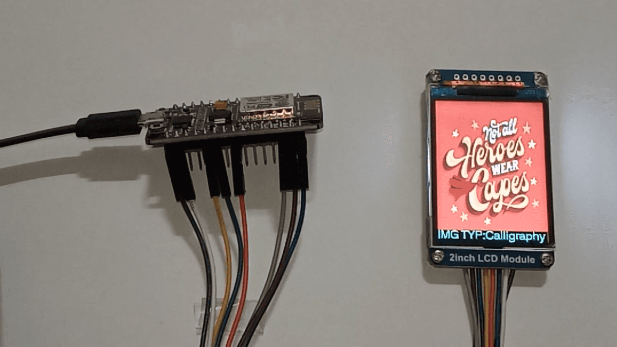
Our aim of this DIY E-Project is to display images in portrait mode, followed by a text indicating the type of each image, namely calligraphy, animated and an HD photo on the ST7789 IPS module. Take a look at the images which have been selected to be displayed:-
Image type: Calligraphy | Image type: Animated | Image type: HD Photo |
 |  |  |
E-COMPONENTS
Here is a list of all the required electronic components for this DIY E-Project, along with respective purchase links:-
MODEL | E-COMPONENT | PURCHASE LINK |
 | NodeMCU ESP8266 | |
 | ST7789 LCD Colour Display Module | |
 | USB data cable | |
 | Power bank |
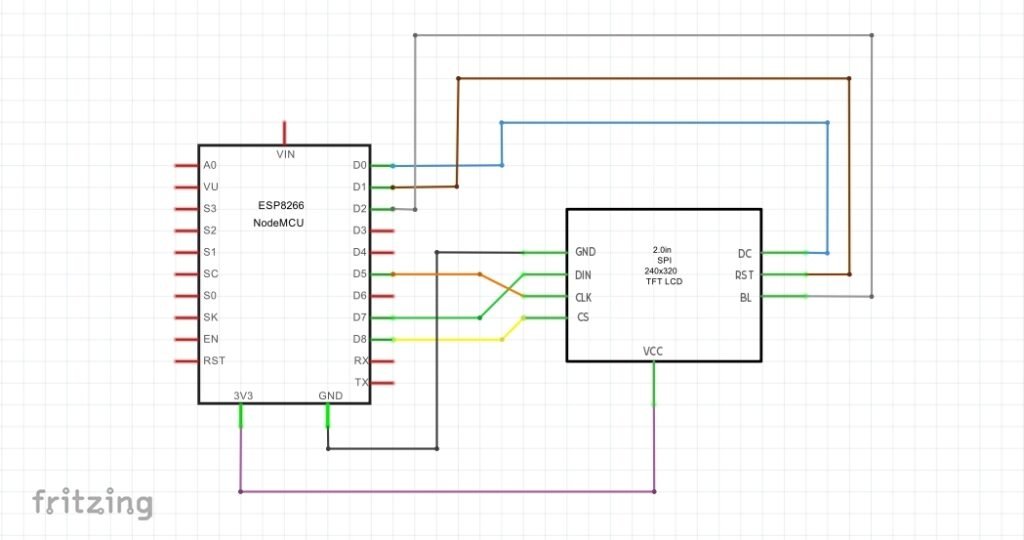
CIRCUIT DIAGRAM

SCHEMATIC DIAGRAM
PROCEDURE
These are some of the step-by-step guidelines to be followed for this DIY E-Project:
- Install the latest Arduino IDE.
- Install the ESP8266 library in the Arduino IDE.
- Download the modified TFT_eSPI library .ZIP file from here →TFT_eSPI (Note: Kindly download the TFT_eSPI library from here itself as its User_Setup.h file has been updated to get assured results as per this DIY E-Project. Else, you can download the TFT_eSPI library .ZIP file from the link https://github.com/maditnerd/st7789_bitmap and make your modifications manually.)
- In Arduino IDE, go to Sketch→Include Library→Add .ZIP Library and install the modified TFT_eSPI library in Arduino IDE.
- Make hardware connections as per the above circuit and schematic diagrams.
- Connect the ESP8266 to your Laptop/PC via USB data cable. In Arduino IDE, go to Tools and select Board as NodeMCU 1.0 (ESP-12E Module) and COM port accordingly.
- Download the folder containing the sketch and images header files from here → Display_images_on_ST7789_IPS_module_sketch . Make sure to save all the image header files in the same folder as your sketch. (Note: kindly download the folder from here itself to get assured results as per this DIY E-Project. Else follow the instructions as mentioned in the link https://www.hackster.io/usini/display-images-on-a-st7789-screen-fbb0d7 .)
- Upload the “Displaying Images on ST7789 IPS module sketch” from the programming section below to NodeMCU.
- Optionally, after the completion of the program upload, you can plug off the USB data cable connected from the ESP8266 to the Laptop/PC and again connect it from the ESP8266 to a Power bank.
PROGRAMMING
SKETCH 1: Displaying Images on ST7789 IPS module sketch
/*
 *Display images on ST7789 IPS module
 *Made by www.wiztaqnia.com
 *Modified date: 29/09/2022
 *Typical pin layout used:
 * ---------------------------------------------
 * Signal               ST7789 IPS    ESP8266
 *                      Module        Interface
 *                      Pin           Pin
 * ---------------------------------------------
 * VCC(3.3V)            VCC           3V3
 * GND(Ground)          GND           GND
 * SDA(Serial Data)     DIN           D7(MOSI)
 * SLK(Serial Clock)    CLK           D5(SCLK)
 * CS(Chip Select)      CS            D8(CS)
 * DC(Data/Command)     DC            D0
 * RST(Reset)           RST           D1
 * BL(Backlight)        BL            D2
  */

#include <TFT_eSPI.h>
#include "Not_all_heros_wear_capes_lettering.h" //Image 1
#include "Metaverse.h"                          //Image 2
#include "Flower_pot_with_flowers.h"            //Image 3
TFT_eSPI ipsdisp= TFT_eSPI();

void setup() {
 Serial.begin(115200);        //Initialise UART Communication with 115200 bits/s Baud Rate
 ipsdisp.begin();             //Initialise SPI Bus
 ipsdisp.init();              //Initialise ST7789
 ipsdisp.setRotation(2);      //Value 1 means landscape mode; Value 2 means portrait mode
 ipsdisp.setSwapBytes(true);  //Swap the byte order for pushImage() - corrects endianness
 ipsdisp.fillScreen(TFT_WHITE);
}

void loop() {
 ipsdisp.pushImage(0,0,240,320,image1);    //ipsdisp.pushImage(x1,y1,x2,y2,array of image 1 containing 16-bit RGB565 data of each pixel)
 ipsdisp.setCursor(0,295,4);               //ipsdisp.setCurser(x axis,y axis,text font style i.e. 1/2/4/6)
 ipsdisp.setTextColor(TFT_CYAN,TFT_BLACK); //ipsdisp.setTextColor(text color,text background color)
 ipsdisp.println(F("IMG TYP:Calligraphy  "));
 delay(10000);
 ipsdisp.pushImage(0,0,240,320,image2);    //ipsdisp.pushImage(x1,y1,x2,y2,array of image 2 containing 16-bit RGB565 data of each pixel)
 ipsdisp.setCursor(0, 295,4);              //ipsdisp.setCurser(x axis,y axis,text font style i.e. 1/2/4/6)
 ipsdisp.setTextColor(TFT_CYAN,TFT_BLACK); //ipsdisp.setTextColor(text color,text background color)
 ipsdisp.println(F("IMG TYP:Animated     "));
 delay(10000);
 ipsdisp.pushImage(0,0,240,320,image3);    //ipsdisp.pushImage(x1,y1,x2,y2,array of image 3 containing 16-bit RGB565 data of each pixel)
 ipsdisp.setCursor(0,295,4);               //ipsdisp.setCurser(x axis,y axis,text font style i.e. 1/2/4/6)
 ipsdisp.setTextColor(TFT_CYAN,TFT_BLACK); //ipsdisp.setTextColor(text color,text background color)
 ipsdisp.println(F("IMG TYP:HD Photo     "));
 delay(10000);
}
OUTPUT
This post was inspired by https://www.hackster.io/usini/display-images-on-a-st7789-screen-fbb0d7
References:
- https://www.waveshare.com/wiki/2inch_LCD_Module
- https://github.com/Bodmer/TFT_eSPI
- https://ifixscreens.com/amoled-vs-ips-lcd-does-display-technology-matter/
- https://arduino.stackexchange.com/questions/24648/how-to-determine-flash-size

Follow her socials: Linkedin | Instagram | GitHub
- Explore Electronic Design Simulators with Arduino MAX7219 Heart Match Game - January 26, 2026
- Word Clock using MAX7219 LED Dot Matrix Display - November 23, 2025
- The Future of Quantum Computing: What Will We Choose to Do? - September 27, 2025