Sometimes, when you purchase a new ESP8266 NodeMCU CP2102 board, you are unable to upload any sketch to it. On this board is a chip CP2102, which is used to implement a USB-to-UART bridge that enables the USB programming ability of the board.
This chip, CP2102, requires a USB-to-serial driver, typically not installed on Windows or MAC OS computers/laptops. Hence, we need to install this driver manually to upload a sketch to the NodeMCU board.
These are some of the guidelines that you can follow to install a USB-to-serial driver for Windows OS and upload your sketch to the NodeMCU board:-
- In Arduino IDE, go to File →Preferences. Copy(Ctrl+C) and paste(Ctrl+V) this URL “https://arduino.esp8266.com/stable/package_esp8266.com_index.json” in the Additional Board Manager URLs row and click on →OK.
- In Arduino IDE, go to Tools →Boards: →Board Manager. Search for “esp8266” by esp8266 community →Install→Close.
- Go to https://www.silabs.com/developers/usb-to-uart-bridge-vcp-drivers→Downloads →Select CP210x VCP Windows. Download this zip file and extract its contents.

- Run CP210xVCPInstaller_x64/x86 depending on your Windows OS architecture, i.e. x64 or x86, and install.

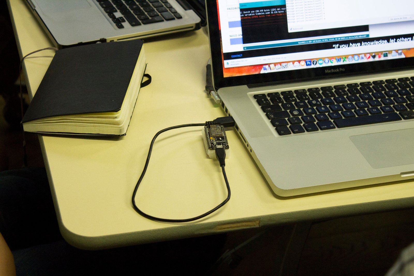
- Restart the Arduino IDE. Connect the NodeMCU board to your computer/laptop via USB data cable. If connected properly, you should hear a notification sound on your computer/laptop. Also, if the NodeMCU board is working optimally, its BUILTIN-LED will flash once.
- Now, go to Computer →Right-click and go to Properties →Device Manager →Ports (COM &LPT) →Silicon Labs CP210x USB to UART Bridge (COM10). When you can view this option, it means that your NodeMCU has been successfully recognised by your Windows OS via a USB-to-serial driver. Note that the COM port number may be different depending on your computer/laptop.

- If the installation is successful, the NodeMCU connected via USB data cable to your computer/laptop will be detected by the Windows OS.
- In Arduino IDE, go to File →Examples →ESP8266 →Blink.
- In Arduino IDE, go to Tools →Boards: →NodeMCU 1.0 (ESP-12E Module) →Port →COM10. Again, note that the COM port number may differ depending on your computer/laptop.
- Compile the sketch and upload the sketch to the NodeMCU board.

Noor Fatimah Iqbal Husain is the visionary behind Wiztaqnia. As a Technical Writer with a strong background in electronics and a passion for programming, she creates engaging, accessible content that simplifies complex electronics and cutting-edge technology. Her dedication to continuous learning and ethical technology use empowers organizations to innovate and thrive. Connect with her to elevate your understanding of technology and bring clarity to the intricate world of electronics.
Follow her socials: Linkedin | Instagram | GitHub
Follow her socials: Linkedin | Instagram | GitHub
Latest posts by Noor Fatimah I.H (see all)
- Explore Electronic Design Simulators with Arduino MAX7219 Heart Match Game - January 26, 2026
- Word Clock using MAX7219 LED Dot Matrix Display - November 23, 2025
- The Future of Quantum Computing: What Will We Choose to Do? - September 27, 2025