Explore a fun and engaging way to see the time with a word clock! Learn how to build your own word clock using the MAX7219 LED dot matrix display, enhancing not only your DIY skills but also your understanding of coding and electronics. Let’s reimagine our perception and interaction with time, making each hour a joyful moment in our daily lives.
Wouldn’t it be much cooler if our clocks displayed the time in words instead of digits? I mean, it is 2025, right? I can already imagine waking up to “It’s 1 o’clock” flashing on my Word Clock using MAX7219 LED Dot Matrix Display instead of just numbers. It would make checking the time a more entertaining experience by transforming traditional time-telling.
I mean, have you heard anyone say it’s “1:08”? It sounds quite funny, right? Even though we don’t have control over time, we humans have a unique way of telling time. We love to assign words and phrases to different times of the day, making each hour feel distinct and memorable.
Let’s create a simple and intuitive Word Clock using the MAX7219 LED display. Take a look at some of the jargon you might come across in this DIY E-Project:
The DS3231 RTC Module synchronises to the exact date and time at which it was programmed and continues counting from that point on. Additionally, it utilises a coin cell as a fail-safe measure to maintain the time even during power loss or reboots.
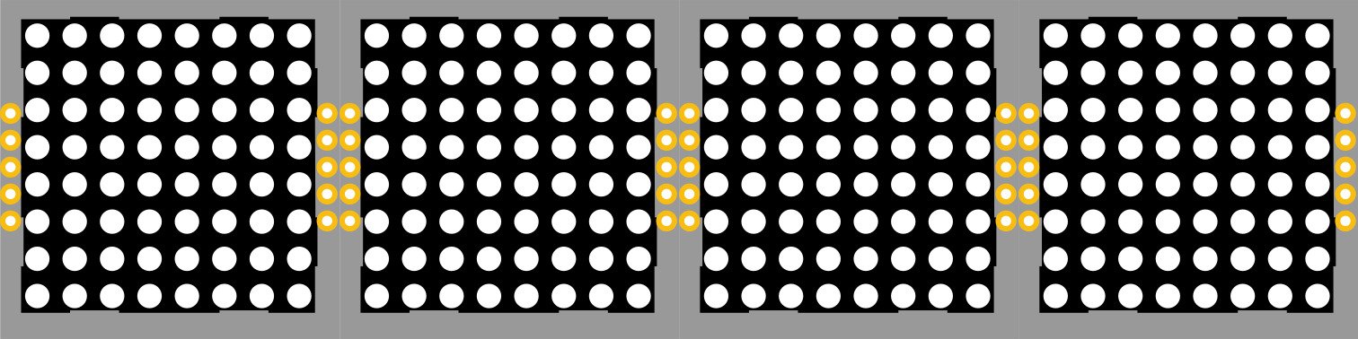
MAX7219 LED Dot Matrix 4-in-1 Display is an expandable display consisting of four individual LED Dot Matrices, made up of tiny monochrome red LEDs (up to 64 LEDs in a single matrix), each controlled by a MAX7219 breakout board. The best part is that you can customise the size by daisy-chaining numerous panels together to create larger visual displays. Make sure to keep the brightness low and use an external power supply to power these panels in case you are planning on using multiple display panels, and avoid overheating.
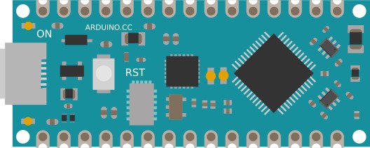
Arduino Nano Every is a compact, breadboard-friendly microcontroller that’s perfect for embedded systems and prototyping. It runs on the ATmega4809, offering more memory and flexibility than the classic Arduino Nano, and supports both I²C and SPI—making it ideal for interfacing with sensors, displays, and real-time clocks.
Explore the IoT Related DIY E-Project: IoT based Indoor Air Quality ENS160 Monitor
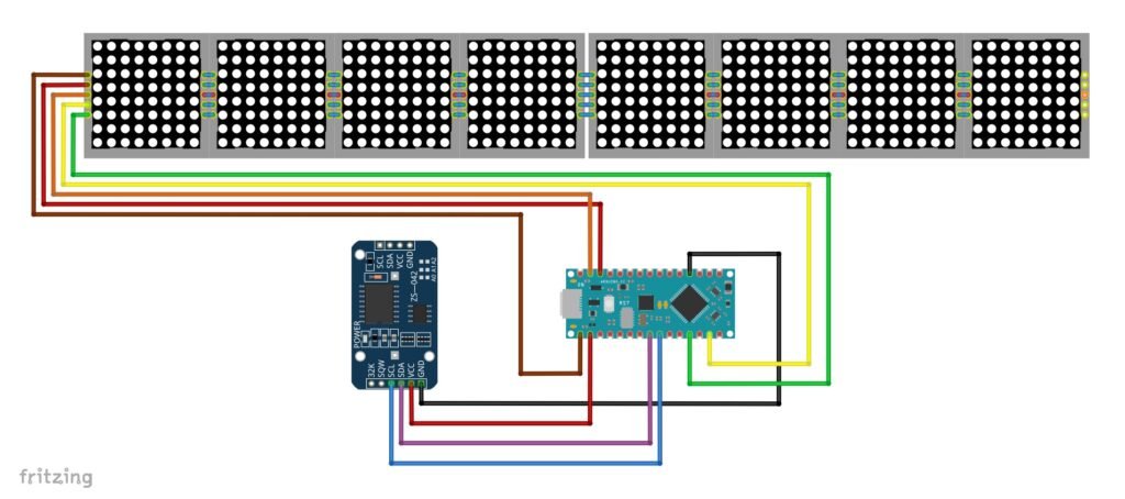
This is the concept behind the Word Clock using MAX7219 Dot Matrix LED Display. When powered on, the DS3231 RTC module starts tracking the current time and date. It sends this data to the Arduino Nano Every via I²C communication. Once the Arduino receives the data, it immediately forwards it to the MAX7219 LED Dot Matrix 4-in-1 Display using SPI communication. Two of these 4-in-1 display panels are daisy-chained to allow longer text to display across the full width.
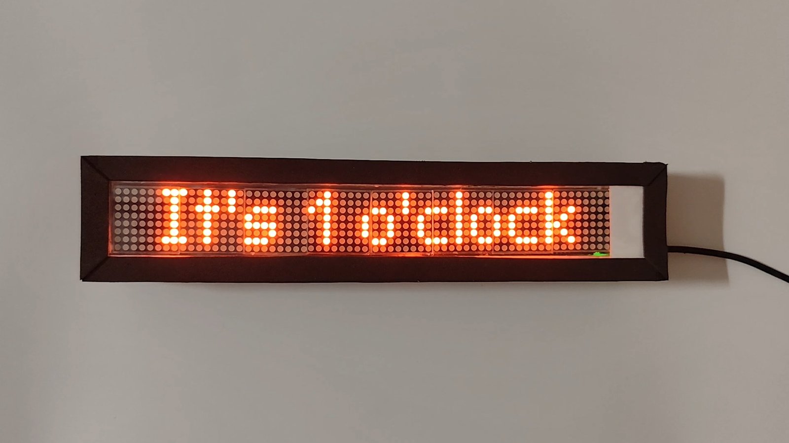
This data exchange happens continuously at regular intervals, with the time being updated every second. By default, the display shows numeric time like a regular digital clock. But every quarter hour, the time is projected in words scrolling from left to right. For example:
- 00→”It’s 1 o’clock”
- 15→”Quarter past 1″
- 30→”Half past 1″
- 45→”Quater to 2″
In order to create these animations and text effects, Arduino Nano Every has been programmed to send special instructions to the MAX7219 LED Dot Matrix Display with the help of the MD_Parola library.
This DIY E-Project is designed to display time in a standard digital format, while also switching to a time-in-words format at key intervals for added clarity and variety. This creative approach to showing time not only enhances engagement but also makes timekeeping more interesting and enjoyable.
E-COMPONENTS
These are all the electronic components that are required for this DIY E-Project and their purchase links:
MODEL | E-COMPONENT | PURCHASE LINK |
 | Arduino Nano Every | |
 | MAX7219 LED Dot Matrix 4 in 1 Display | |
DS3231 RTC Module | ||
CR2032 Coin Cell | ||
USB Female to Micro USB/USB Type C Connector | ||
 | USB data cable | |
Power Bank |
For creating the outer case, here are the products required along with their purchase links:
PRODUCT | PURCHASE LINK |
OHP Sheet | |
Black Foam Sheet | |
Half Inch Thermocol Sheet |
CIRCUIT DIAGRAM
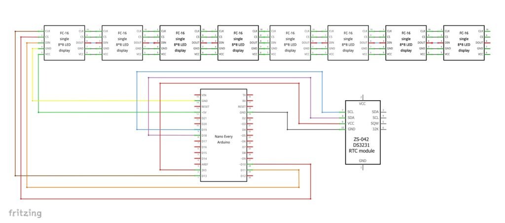
SCHEMATIC DIAGRAM
PROCEDURE
Setting up time in the DS3231 RTC Module:
If you find that the time being displayed is not according to the actual time, then here’s what you can do:
- Hard-code the current time and date into the sketch before uploading it.
- Include this line of code inside the
void setup(){}function of the sketch and manually enter the correct values following the format (year, month, day, hour, minutes, seconds), as shown below:void setup(){ rtc.adjust(DateTime(2025, 8, 4, 12, 45, 0)); // YYYY, MM, DD, HH, MM, SS } - Upload this line once, then comment it out so it doesn’t reset every time.
Thankfully, the time displayed remains accurate as long as the power supply (in this case, a power bank) does not disconnect. However, the moment you unplug the Power Bank, the RTC loses power and resets to the default time (often Jan 1, 2000).
To prevent this from happening, make sure to use a coin cell to power the DS3231 RTC module so that it can continue to count time correctly without resetting after every restart.
These are some of the step-by-step guidelines to be followed for this DIY E-Project:
- Install the latest Arduino IDE.
- From the Board Manager→Install “Arduino megaAVR Boards.”
- Install all the latest versions of these dependencies in the Arduino IDE. (Note: Make sure to click on the “Install All” button instead of “Install without dependencies” when prompted to avoid encountering any errors while debugging):-
1.MD_Parola
2.MD_MAX72XX
3.RTClib
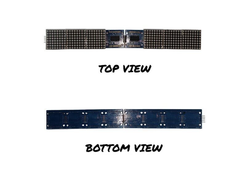
- Make hardware connections as per the above circuit and schematic diagrams. To daisy chain two MAX7219 LED Dot Matrix 4-in-1 Display Panels, here’s what you can do:
- For the first display panel, find the DIN side where the headpins are attached.
- Detach its dot matrix LED segment to expose the MAX7219 breakout board underneath.
- For the second display panel, find the DOUT side. Similarly, detach its dot matrix LED segment to expose the MAX7219 breakout board underneath.
- Bend the header pins such that DOUT of the first display panel connects to DIN of the second panel while sharing VCC, GND, CLK, and CS pins of both the panels.
- Solder this joint. After letting it cool, carefully reattach the dot matrix LED segments to the respective positions. (Note: in case you have no prior soldering experience, simply get it soldered from your local electronic repair shop.)
- Once done, your display will look like this:
- As a precaution, screw the two MAX7219 LED Dot Matrix 4-in-1 Display Panels onto an MDF board to secure the solder joint from coming off. A cheaper option is using normal hard cardboard instead.
- Connect the Arduino Nano Every to your Laptop/PC via a USB data cable. In Arduino IDE, go to Tools→Board→Arduino megaAVR Boards and select Board as Arduino Nano Every and COM port accordingly.
- Upload the sketch “Word Clock using MAX7219 LED Dot Matrix Display” from the programming section to the selected Arduino Nano Every board.
- After completing the program upload, you can unplug the USB data cable connected from the Arduino Nano Every to the Laptop/PC and reconnect it from Arduino Nano Every to the Power bank.
- Watch the magic unfold as you witness your Word Clock using MAX7219 LED Dot Matrix Display come to life!
If you also want to get creative and build your outer case without the hassle of 3D printing, follow these steps to make the outer covering of the display:-
- Measure cut the thermocol sheet and glue the box as required.
- Cover the exposed thermocol side with a black foam sheet. (Note: Preferably choose black for the light from the display panel to reflect better.)
- Measure cut the OHP sheet, and cover the top of the outer case where the 2X MAX7219 LED Dot Matrix 4-in-1 Display Panels will be placed.
- Make an insertion at the bottom of the box for the data cable.
- Place all the electronic components inside and secure their position by inserting extra thermocol pieces and using strong tape.
PROGRAMMING
Sketch 1: Word Clock using MAX7219 LED Dot Matrix Display
/*
 * Word Clock using MAX7219 LED Dot Matrix Display
 * Made by www.wiztaqnia.com
 * Modified date: 23/11/2025
 * Typical pin layout used:
 * ----------------------------------------------------------
 * Signal              MAX7219 LED       DS3231     Arduino
 *                      Dot Matrix        RTC        Nano
 *                    4-in-1 Display     Module      Every
 * ----------------------------------------------------------
 * 3.3V                    --             VCC         3V3
 * 5V                      5V             --          +5V
 * GND(Ground)             GND            GND         GND
 * DIN (Data Input)        DIN            --          D11
 * CS (Chip Select)        CS             --          D10
 * CLK (Clock)             CLK            --          D13
 * SCL (Serial Clock)      --             SCL         A4
 * SDA (serial Data)       --             SDA         A5
 */
#include <MD_Parola.h>     //Handles text effects
#include <MD_MAX72XX.h>    //MAX7219 driver
#include <SPI.h>
#include <Wire.h>
#include <RTClib.h>


#define DISPLAY_TYPE MD_MAX72XX::FC16_HW  //Define the type of LED Dot Matrix Display used i.e. GENERIC_HW or FC16_HW
#define MATRICES 8                        //Define the total number of LED Dot Matrix Modules used. Each matrix consists of 64 LEDs

// Define SPI pins
#define DATA_PIN 11
#define CLK_PIN  13
#define CS_PIN   10


MD_Parola clockFace = MD_Parola(DISPLAY_TYPE, CS_PIN, MATRICES);  //MD_Parola(HARDWARE_TYPE,CS_PIN,MAX_DEVICES)
RTC_DS3231 clock;

void setup() {
  Wire.begin();      //Initialize I2C communication
  clock.begin();     //Initialize RTC module

  // Set RTC to compile time if it lost power
  if (clock.lostPower()) {
    clock.adjust(DateTime(F(__DATE__), F(__TIME__)));
  }


  clockFace.begin();                      //Initialize LED Dot Matrix display
  clockFace.setIntensity(8);              //Set the brightness of the LED Dot Matrix. The range of brightness is 0 to 15
  clockFace.displayClear();               //Clear the LED Dot Matrix display
  clockFace.setTextAlignment(PA_CENTER);  //Center align text
}

// Return time in words for every quarter of an hour
String timeInWords(int hour, int minute) {
  int h = hour % 12;
  if (h == 0) h = 12;

  switch (minute) {
    case 0:  return "It's " + String(h) + " o'clock";
    case 15: return "Quarter past " + String(h);
    case 30: return "Half past " + String(h);
    case 45: return "Quarter to " + String((h % 12) + 1);
    default: return "";
  }
}

void loop() {
  DateTime now = clock.now();
  int hour = now.hour();
  int minute = now.minute();
  bool isPM = hour >= 12;

  // Convert to 12-hour format
  int displayHour = hour % 12;
  if (displayHour == 0) displayHour = 12;
  String phrase = timeInWords(hour, minute);  //Show time in words for every quarter of an hour

  if (phrase != "") {
    clockFace.setTextAlignment(PA_CENTER);                                 //Center align text
    clockFace.displayScroll(phrase.c_str(), PA_LEFT, PA_SCROLL_LEFT, 50);  //display.displayscroll(pText,align.textEffect,speed)
    while (!clockFace.displayAnimate()) {                                  //Wait for scroll to finish

    }
  } else {

    char timeString[20];
    sprintf(timeString, "%02d%c%02d %s %d/%d",    //Time display Format: "HH:MM AM/PM Day/Month" with blinking colon
            displayHour,
            (now.second() % 2 == 0) ? ':' : ' ',  //Blink the colon
            minute,
            isPM ? "PM" : "AM",
            now.day(), now.month());

    clockFace.displayReset();                //Reset scroll mode
    clockFace.setTextAlignment(PA_CENTER);   //Center align text
    clockFace.displayText(timeString, PA_CENTER, 0, 0, PA_PRINT, PA_NO_EFFECT); //displayText(pText,align.textEffect,startPosition,endPosition,displayMode.staticText,animationEffect.noTransition)
    clockFace.displayAnimate();              //Scroll the text
  }

  delay(1000);  //Update every second
}
OUTPUT
This post was inspired by DIY Word Clock – 3D Printed – (Arduino Nano, RTC DS3231 and Adafruit Neopixel)
References:
- https://lastminuteengineers.com/max7219-dot-matrix-arduino-tutorial/
- https://youtu.be/mbTvvefux_4?si=6LqGgSKEumkm_Oji

Follow her socials: Linkedin | Instagram | GitHub
- Explore Electronic Design Simulators with Arduino MAX7219 Heart Match Game - January 26, 2026
- Word Clock using MAX7219 LED Dot Matrix Display - November 23, 2025
- The Future of Quantum Computing: What Will We Choose to Do? - September 27, 2025